Remeha Avanta Plus p Series User Manual Page 1
Browse online or download User Manual for Power extensions Remeha Avanta Plus p Series. Remeha Avanta Plus P SERIES Installation and Service Manual
- Page / 24
- Table of contents
- BOOKMARKS
- Package RC 6 1
- Contents 2
- 1Introduction 3
- 1.3 Directive 97/23/EC 4
- 2 Technical description 5
- 3 Electrical connections 6
- 3.1 Terminal block 7
- C002871-A 8
- C002872-A 8
- 3.2.2 Connections 9
- 2x 0,75 mm 12
- M0 40016 14
- 3.10 Connecting the burner 15
- B4 S3 T2 T1 N 16
- 4 Skeleton Diagrams 17
- P320 - P420 - P520 18
- 5 Starting up and operation 20
- 6 Spare parts 22
- © Copyright 24
- Subject to alterations 24
Summary of Contents
Package RC 6Control panelInstallation and Service Manual300023031-001-AEN30l001M00 34
10Control panel RC6 06/01/10 - 300023031-001-AConnection block for Rematic sensors and controls.ZSee the instructions supplied with the control unit a
1106/01/10 - 300023031-001-A Control panel RC63.2.3 Mouting of the control unit- Bring the blue connectors out through the opening in the controlpanel
12Control panel RC6 06/01/10 - 300023031-001-A3.3 Connecting a third party control unitControl of the first stage of the burner by volt-free contact
1306/01/10 - 300023031-001-A Control panel RC63.5 Connecting the low-water pressure switch alarm indicator (Only NL)Low-water pressure switch alarm
14Control panel RC6 06/01/10 - 300023031-001-A3.8 Connecting one or two hour run meters (Package BG 40)One or two optional hour run meters (stage 1 an
1506/01/10 - 300023031-001-A Control panel RC63.9 Connecting the flue gas thermometer (Package BP 28)An optional flue gas thermometer may be fitted on
16Control panel RC6 06/01/10 - 300023031-001-A3.10.1 Burner without plug-in connectorsIn this case, the connectors supplied with the burner cable must
1706/01/10 - 300023031-001-A Control panel RC64 Skeleton Diagrams4.1 Principle diagram of the control panelSCHEMA DE PRINCIPE - STROMLAUFPLAN - PRINC
18Control panel RC6 06/01/10 - 300023031-001-A4.2 Principle diagram of control panel with optional Rematic control unitSCHEMA DE PRINCIPE - STROMLAUF
Control panel RC6 06/01/10 - 300023031-001-AA Boiler pump TCH1 Stage 1 boiler thermostatB Burner TCH2 Stage 2 boiler thermostatBA Terminal TS Safety
ContentsControl panel RC6 06/01/10 - 300023031-001-A1 Introduction . . . . . . . . . . . . . . . . . . . . . . . . . . . . . . . . . . . . . . . . . .
20Control panel RC6 06/01/10 - 300023031-001-A5 Starting up and operation5.1 Control panel without Rematic control unitThe first start-up is to be pe
2106/01/10 - 300023031-001-A Control panel RC65.2 Control panel with optional Rematic control unitThe first start-up is to be performed by your insta
Control panel RC6 06/01/10 - 300023031-001-A6 Spare partsTo order a spare part, quote the reference number next to the part required.06/01/10 - 3000
2306/01/10 - 300023031-001-A Control panel RC6Ref. Code no. DescriptionControl panel1 8555-0527 Painted control panel base2 8555-0536 Painted control
© CopyrightAll technical and technological information contained in these technical instructions, as well as anydrawings and technical descriptions su
306/01/10 - 300023031-001-A Control panel RC61Introduction1.1 Symbols and abbreviationsCaution dangerRisk of injury and damage to equipment. Attentio
4Control panel RC6 06/01/10 - 300023031-001-A1.3 Directive 97/23/ECGas and oil boilers with a maximum operating temperature of 110°Cand hot water tank
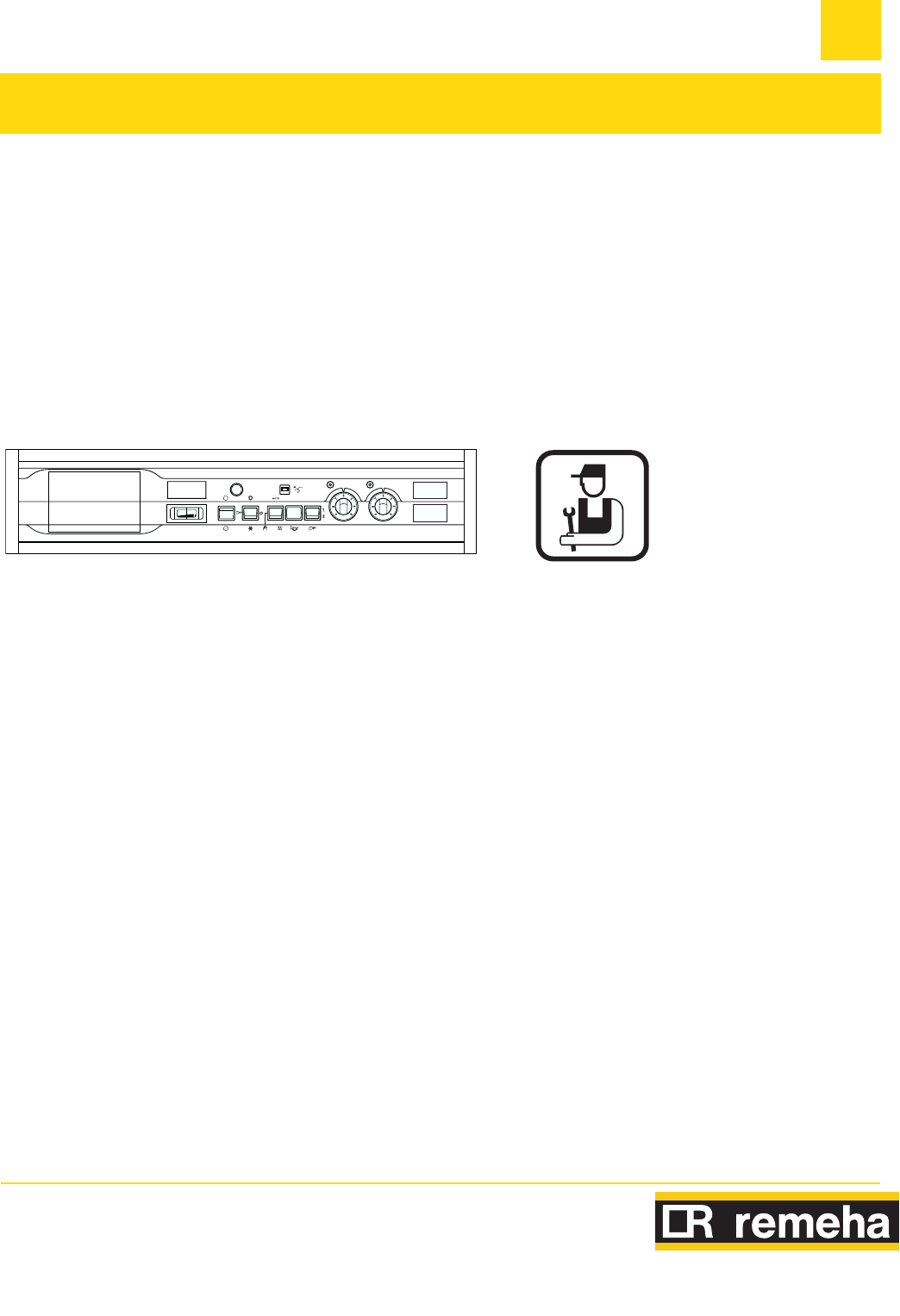
506/01/10 - 300023031-001-A Control panel RC62 Technical description2.1 General descriptionThe control panel is used to control boilers with 1 or 2-st
6Control panel RC6 06/01/10 - 300023031-001-A2.3 Operating principle2.3.1 Boiler regulationThe boiler may be regulated:- either by the boiler thermost
706/01/10 - 300023031-001-A Control panel RC63.1 Terminal blockAll connections are made with the terminal boxxes designed for thatpurpose on the back
8Control panel RC6 06/01/10 - 300023031-001-A3.2 Installation with optional Rematic control unit3.2.1 Fitting the Rematic control unitThe Rematic cont
906/01/10 - 300023031-001-A Control panel RC6Installing the supplementary wiring3.2.2 ConnectionsMake the electrical connections.230 V main supply
More documents for Power extensions Remeha Avanta Plus p Series

© 2020, manymanuals.com. All rights reserved. | 0.496 s |
 Manymanuals.com
 Manymanuals.de
 Manymanuals.fr
 Manymanuals.it
 Manymanuals.pl
 Manymanuals.cz
 Manymanuals.es
 Manymanuals-pt.com
Comments to this Manuals